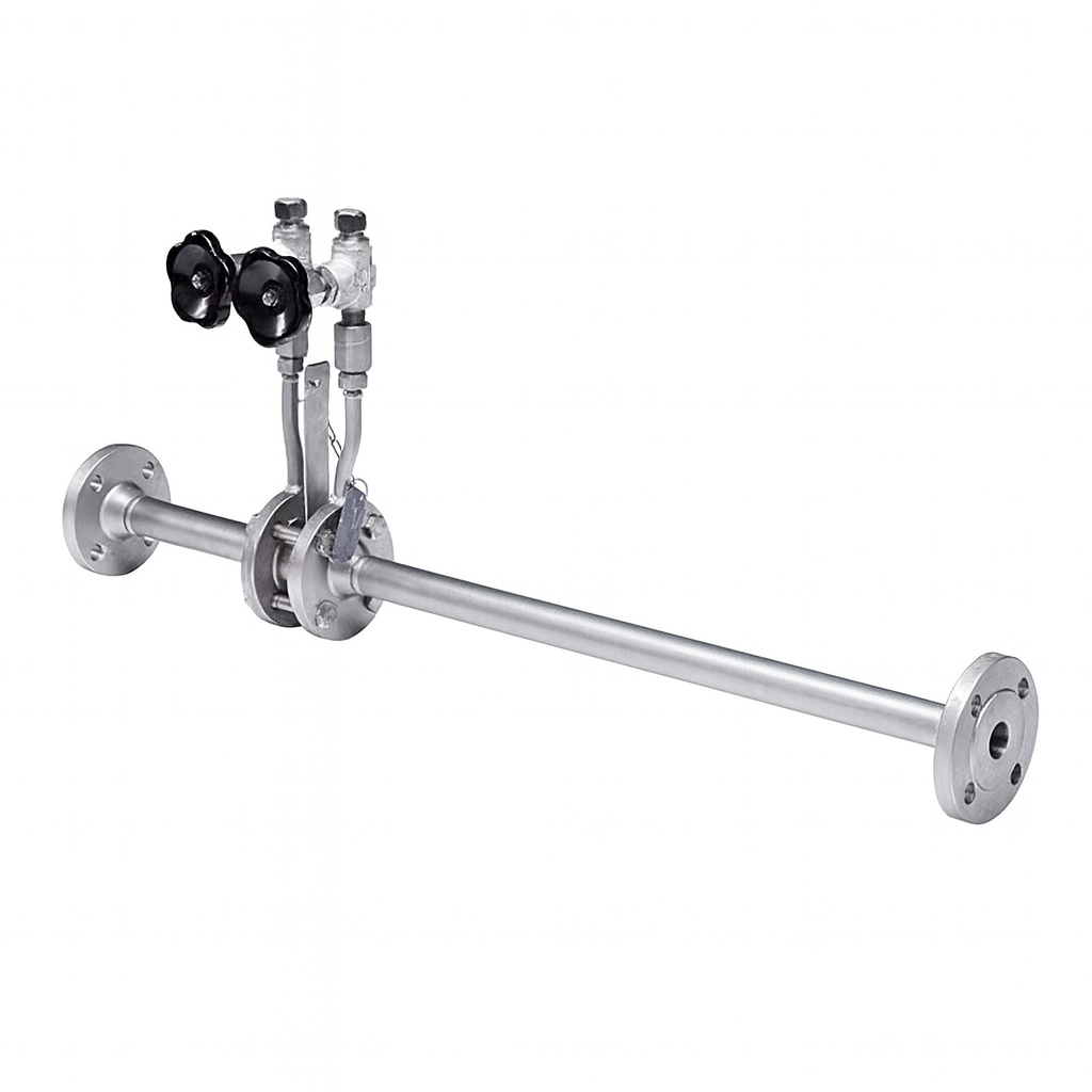
Differential pressure flow meters are used in many industrial applications. When high measurement accuracy is required, the optimum solution for primary flow elements is a meter run.
A meter run is an assembly consisting of an orifice plate, flanges, and calibrated upstream and downstream pipe sections. Since the meter run is manufactured as a single unit, all components are optimally matched to one another. This eliminates deviations that could otherwise lead to measurement errors.
Optimum Solution for Every Application
According to the standards, the term "meter run" is used only for small pipe sizes up to 1½ inches in diameter.
Regardless of pipe size, mounting type, pressure tapping location, or transmitter connection configuration, meter runs provide a reliable and accurate flow measurement solution.
Applications
Power Generation
Oil Production and Refining
Water Treatment and Distribution Systems
Gas Processing and Transmission Pipelines
Chemical and Petrochemical Industries
Special Features
Maximum operating temperature and pressure are limited by the selected material and pressure class.
Suitable for measuring liquid, gas, and steam flow.
Measurement accuracy: ≤ ±1.0% of actual flow.
Repeatability: ±0.1%.
Meter Run
General Specifications
Nominal Size
Can be manufactured in accordance with all relevant standards.
Nominal Pressure Rating
Can be manufactured in accordance with all relevant standards.
Pipe Schedule
The pipe wall thickness must be specified by the customer.
Materials
Specified separately in the specifications for each model.
Pressure Tappings
Specified separately in the specifications for each model.
Sealing Faces
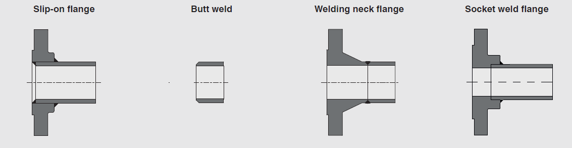
Slip-on flange: ANSI Class 150, 300
Welding neck flange (Raised Face): Class 150–2500
Welding neck flange (Ring Type Joint): Class 150–2500
Other pressure classes are available upon request.
Mounting Options
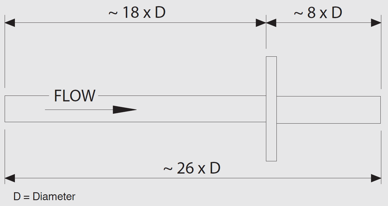
Length Rule
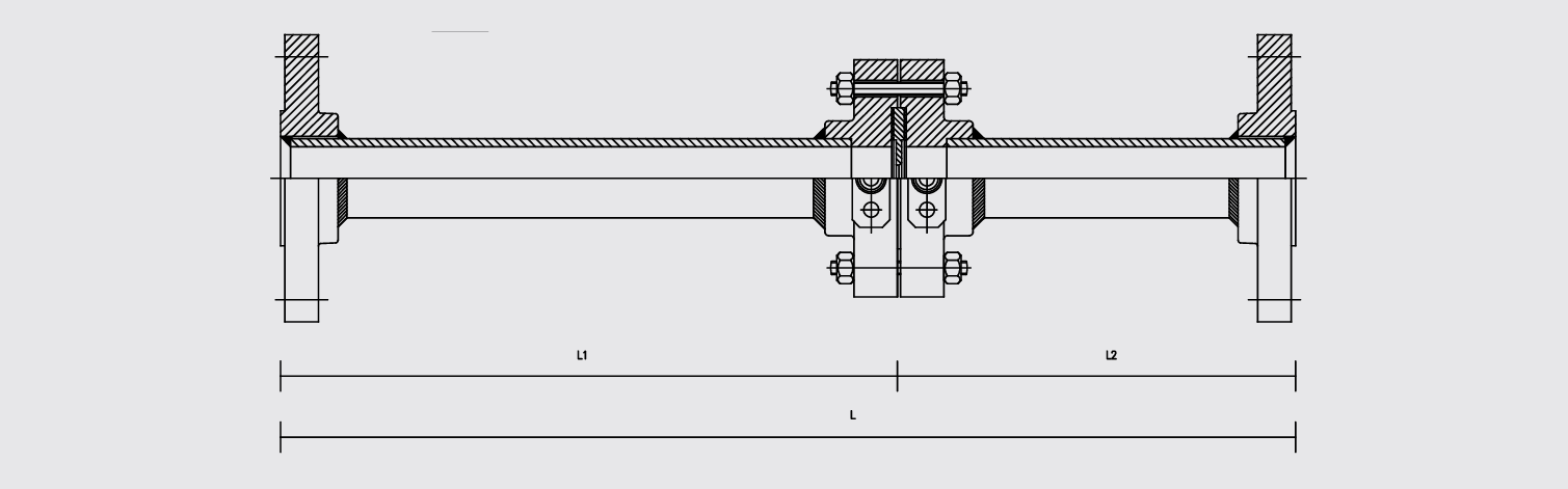
The standard requirements for the lengths of the upstream and downstream pipe sections are illustrated in the diagram below:
D = Pipe Diameter
Pipe Lengths
Value
upstream
Approximate 18 × D
downstream
Approximate 8 × D
Total Length
Approximate 26 × D
Akış yönü: FLOW →
Technical Specifications (Meter Run with Integral Orifice)
Nominal Size
¼" ... 1½" (DN 15 ... 40)
Pressure Tappings
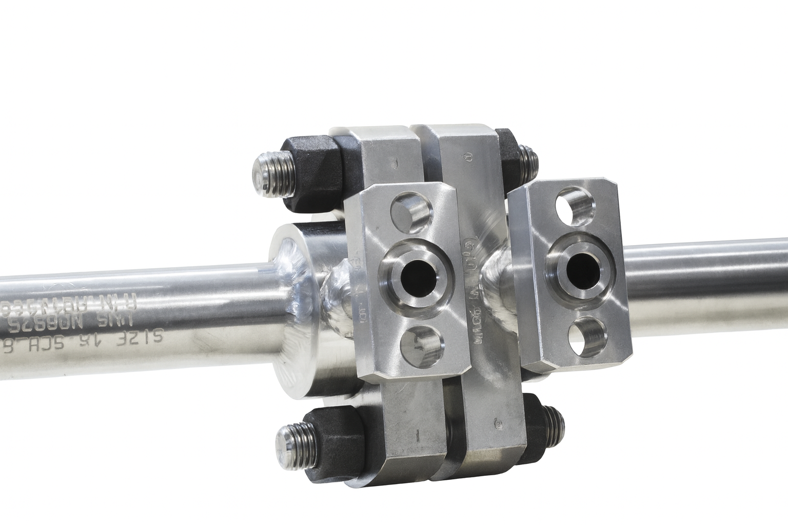
Corner taps
Two oval flanges for direct mounting of the differential pressure transmitter
Entegre Orifis
Materials
Component
Material
Pipe
Stainless Steel 316 / 316L
Pipe flanges
Stainless Steel 316 / 316L
Orifice flanges
Stainless Steel 316 / 316L
Studs
Stainless Steel ASTM A193 Gr. B8
Nuts
Stainless Steel ASTM A194 Gr. 8
Plug
Stainless Steel 316
Sealing
PTFE / Grafit
Orifice plate
Stainless Steel 316 / 316L
Boyutlar (Dimensions)
Tablo: Ölçüler (mm cinsinden) ve ağırlıklar (kg cinsinden)
Nominal Size
L (mm)
L1 (mm)
L2 (mm)
Weight (kg)
½" (DN 15)
550
380
170
5
¾" (DN 20)
700
500
200
8
1" (DN 25)
900
650
250
10
1 ½" (DN 40)
1 300
1 000
300
22
The dimensions shown in the table are independent of the selected mounting type.
The specified weight applies to the slip-on flange configuration.
Meter Run with Slip-on Flanges
Nominal Size
L (mm)
L1 (mm)
L2 (mm)
Weight (kg)
½" (DN 15)
550
380
170
6
¾" (DN 20)
700
500
200
9
1" (DN 25)
900
650
250
11
1 ½" (DN 40)
1 300
1 000
300
23
The weight specified in the table corresponds to the slip-on flange configuration, as shown in the drawing.
Meter Run with Welding Neck Flanges
Nominal Size
L (mm)
L1 (mm)
L2 (mm)
Weight (kg)
½" (DN 15)
600
400
200
10
¾" (DN 20)
700
500
200
14
1" (DN 25)
900
600
300
19
1 ½" (DN 40)
1 300
900
400
40
Model FLC-MR-STD (Standard Meter Run) – Technical Specifications
Nominal Size
½" … 1½" (DN 15 … 40)
Pressure Tappings
Corner taps
Two ½" NPT connections
Materials
Component
Material
Pipe
Stainless Steel 316 / 316L
Pipe flanges
Stainless Steel 316 / 316L
Orifice flanges
Stainless Steel 316 / 316L
Studs
Stainless Steel ASTM A193 Gr. B8
Nuts
Stainless Steel ASTM A194 Gr. 8
Plug
Stainless Steel 316
Sealing
PTFE / Grafit
Orifice plate
Stainless Steel 316 / 316L
Dimensions
Table – Standard Meter Run (FLC-MR-STD):
Nominal Size
L (mm)
L1 (mm)
L2 (mm)
Weight (kg)
½" (DN 15)
550
380
170
6
¾" (DN 20)
700
500
200
9
1" (DN 25)
900
650
250
11
1 ½" (DN 40)
1 300
1 000
300
23
The weight specified in the table corresponds to the welding neck flange configuration.
Special Meter Run
Dimensions
Nominal Size
L (mm)
L1 (mm)
L2 (mm)
Weight (kg)
2" (DN 50)
1 500
1 200
300
25
2 ½" (DN 65)
1 600
1 250
350
38
3" (DN 80)
1 800
1 400
400
51
4" (DN 100)
2 200
1 700
500
82
The dimensions shown in the table are independent of the selected mounting type. The specified weight values correspond to the welding neck flange configuration.
Technical Specifications
Feature
Value / Description
Nominal size
≥ 2" (≥ DN 50)
Pressure tappings
Flange taps
Two ½" NPT connections
Materials
Pipe: Carbon Steel ASTM A106 Grade B
Pipe Flanges: Carbon Steel ASTM A105
Orifice Flanges: Carbon Steel ASTM A105
Stud Bolts: Stainless Steel ASTM A193 Grade B7
Nuts: Stainless Steel ASTM A194 Grade 2H
Plug: Carbon Steel
Gasket: Stainless Steel 316, Graphite, and Carbon Steel
Orifice Plate: Stainless Steel 316 / 316L
Optional Solutions
Available upon request (e.g., with an annular-type meter body).
Ordering Information
Model / Nominal Size / Nominal Pressure Rating / Pipe Schedule / Material / Sealing Face
Cookie Preferences
This site uses only strictly necessary cookies to improve your experience. No analytics or marketing cookies are used.
Privacy Policy